
VIS Hydraulics FRS0.G14



Product specifications
| Product Attributes | Test method | ||
|---|---|---|---|
| Weight (Kg) | 0.01 | ||
| Installation torque (Nm) | 1 To 3 | ||
| Filtration | 20/18/15 ISO 4406 (maximum filtration admitted) | ||
| Orientation | Norestrictions | ||
| Oil Testing Conditions | ISOVG46cSt | ||
| Fluid | Mineral | ||
| Pressure Attributes | Test method | ||
|---|---|---|---|
| Max Pressure (Bar) | 250 | ||
| Flow Attributes | Test method | ||
|---|---|---|---|
| Max Flow (l/min) | 15 | ||
| Viscosities (cSt) | 7.4 To 420 | ||
Product Description
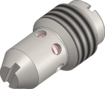
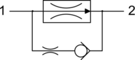
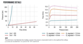
A direct acting, screw-in insert type, 2-way pressure compensated flow control valve. The flow rate of this valve in the 1 to 2 flowpath is largely independent of the system pressure and is determined by the dimension of a calibrated orifice. The valve cannot beadjusted for variable flow output. Free flow in the 2 to 1 path is allowed and not pressure compensated.
Related Documentation
For more information, download the documents below
Request the 3D drawing
Working this component into your own design? Request the STEP file and we'll send it straight to your inbox


